The Importance of Electronic Attack in Modern Electronic Warfare
Standoff jamming, also called electronic attack or high-power ECM, is a crucial element of modern electronic warfare. Unlike “stand-in” systems that operate inside heavily contested areas, standoff systems are employed from a safer distance to shape the electromagnetic environment before friendly forces enter a contested zone. That distance buys survivability, flexibility and the ability to reuse assets across multiple missions.
What Our Antennas Enable
Standoff Distance
Standoff systems can disrupt or degrade enemy radios, radars and datalinks from outside the most dangerous areas, denying the adversary critical sensor and communications capabilities while keeping friendly crews safer.
Multiplicative Effects
Well-executed jamming slows enemy reaction times, forces changes in their tactics, and reduces the effectiveness of their intelligence and targeting, often producing effects that far exceed the resources employed.
Sustained Operations
Vehicle-mounted high-power standoff systems can remain operational longer than stand-in assets, increasing mission tempo and operational persistence.
Coordinated Effects
Effective electronic attack is never isolated. It is coordinated with SIGINT/EW support, ISR, command-and-control and strike or defensive packages so jamming helps friendly communications and navigation while denying the adversary.
Why Our Antennas Perform
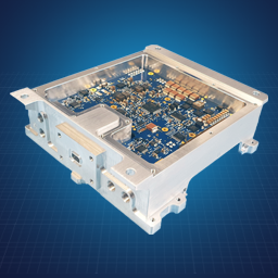
Standoff electronic attack demands antennas that can handle extreme power levels while maintaining pattern integrity across wide bandwidths. Our EA antennas are engineered for high-power jamming applications where reliability, thermal management, and consistent radiation patterns directly determine mission success.
High-Power Handling
Our antennas are built to withstand the continuous high power output required for effective standoff jamming without pattern distortion or thermal failure, ensuring consistent performance throughout extended missions.

Pattern Stability Under Load
Maintaining consistent radiation characteristics at high power levels ensures predictable coverage and effect delivery. Pattern distortion degrades jamming effectiveness; our antennas deliver stable directivity even during sustained high-power operations.
Wide Bandwidth Coverage
Coverage EA operations target multiple threat systems simultaneously across broad frequency ranges. Our antennas maintain gain and pattern stability from VHF through microwave bands, enabling flexible response to evolving threat environments.


What this means for
Your
mission
Electronic attack is only effective when your antennas perform exactly as required, every time. Our EA antenna solutions translate technical performance into operational advantage, giving you the range, power, and reliability needed to shape the electromagnetic battlespace from standoff distances.

1
Mission Flexibility
Wide bandwidth and high power handling mean your platforms can respond to emerging threats without antenna changes, maintaining operational tempo across diverse mission profiles.
2
Crew Survivability
Reliable standoff performance keeps your operators outside high-threat areas while still delivering effects deep into contested zones, reducing risk while maintaining electromagnetic dominance.
3
System Integration
Our antennas integrate cleanly with existing jamming systems and operate alongside ISR, comms, and navigation equipment without interference, enabling true coordinated effects across the electromagnetic spectrum.
Featured products
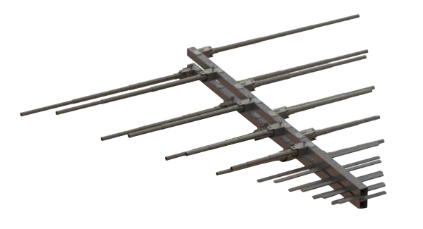
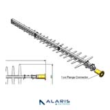
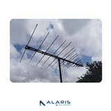
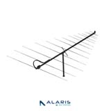
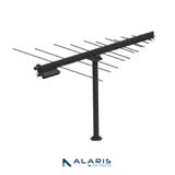
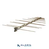
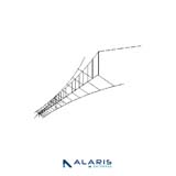
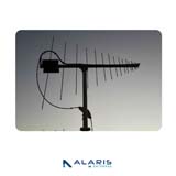
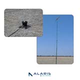
LPDA-A0158
Wideband Modular Foldable LPDA Antenna
The LPDA-A0158 is medium-gain wideband directional LPDA antenna and covers the frequency band from 30 MHz to 512 MHz. The antenna has a modular design which allows the user to deploy either the full assembly or the high frequency section only, depending on the mission requirements. This antenna has foldable elements which makes the antenna easy to stow and deploy. There are no loose parts and no tools required to deploy the antenna. This makes the antenna ideal for tactical applications as well as for use in harsh environments and installations where there is limited space for operators to manoeuvre. All antenna elements are permanently attached to the boom, to prevent any parts from becoming lost in the field.
- Frequency range
- 30 - 512 MHz
- VSWR
- < 2.5:1
- Nominal input impedance
- 50 Ω
- Connector
- 7/16 female
- Feed power handling
- 1000 W
- Gain
- See gain graph
- Polarisation
- Adjustable (vertical or horizontal)
- Dimensions (full assembly - deployed)
- 4810 mm x 182 mm x 5350 mm
- Dimensions (High Frequency section - deployed)
- 1521 mm x 125 mm x 1775 mm
- Total mass
- < 28 kg excl. isolating pole; <43 kg incl. isolating pole.
- Mounting method
- On a swivel bracket fitted to the mast (requires isolation pole to change polarisation which is standard issue)
- Wind survival
- 120 km/h
- Temperature range
- -35°C to +71°C
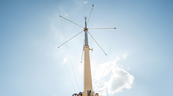
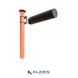
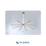
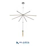
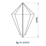
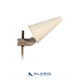
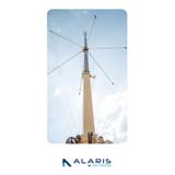
OMNI-A0246
Wideband HF High-Power Antenna System
This is a wideband wire cone monopole antenna that operates over the 1 to 30 MHz band with a VSWR of less than 2.8:1 over the band. The antenna gives a superior radiation pattern for HF signal interception and has been optimized for HF communication. The antenna deploys from a compact enclosure by means of a winch mechanism in less than 220 seconds by a team of as few as 2 people. The antenna can be stowed just as quickly. The antenna is equipped with a sophisticated wideband matching unit which provides excellent VSWR characteristics for best possible efficiency across the band and requires no band switching or other matching control. The design has taken into account the worst-case soil-types and so will work for diverse deployments in deserts, urban areas and wetlands. A groundplane structure of the size of a 20 foot container or larger is suggested for use. All accessories such as matching unit, controller unit etc. are all included with the product.
- Frequency range
- 1 - 30 MHz
- VSWR
- < 2.8:1
- Nominal input impedance
- 50 Ω
- Connector
- EIA 1 5/8
- Feed power handling
- 7.5 kW CW
- Efficiency
- 0 dBi down to 7 MHz, drops off to -30 dBi at 1 MHz
- Polarisation
- Vertical
- Deployed dimensions (Ø x l)
- < 5 m x 14.5 m
- Stowed dimensions (l x w x h)
- 4 m x 1.75 m x 0.87 m
- Mass
- < 700 kg
- Wind survival
- 90 km/hr
- Temperature
- Storage: - 30°C to + 70°C Operational: - 30°C to + 55°C
- Water ingress rating
- MIL-STD-820G, Method 506.6, Procedure I
Products ideal for Electronic Attack Applications


Browse by Application

Counter-UAS Solutions
Advanced detection, location, and jamming capabilities
Digital Broadcasting
High-Linearity Amplifiers for Critical Broadcasting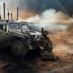
Electronic Countermeasures
Designed to detect, locate, and neutralize hostile signals
Electronic Surveillance
Detection, identification, and emitter tracking
Maritime Antenna Solutions
EW to high-power communication interception
Microwave Ablation
Precision Microwave Energy for Medical Therapy
Plasma Processing
Stable Power for Advanced Plasma Processing
Tactical Communications
Vehicle-to-dismount connectivity
Tactical Direction Finding
Secure communications under jamming and interferenceBrowse by Type
Block Up Converters (BUCs)
Unmatched performance in a compact, fanless design
Communication Antennas
Wide range of HF, VHF, UHF and SHF (L-, S- & C-band)
Direction Finding Antennas
Discover the power of accurate angles of arrival
Low Noise Amplifiers
High-power, low-distortion performance for critical comms.
Low Noise Block Down Converters
Precision RF energy for medical and industrial excellence.
Microwave Power Generators
Reliable satellite signal reception in the toughest environments.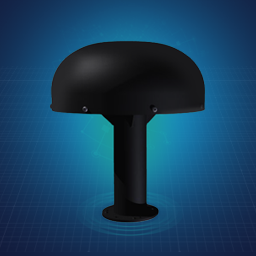
Monitoring Antennas
Spectrum monitoring, signal reception & detection & ITU
Oscillators
Ultra-low phase noise oscillators with exceptional frequency stability
Power Amplifiers
Extract clarity from the faintest RF signals.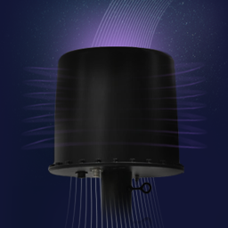
Steerable Beam Antennas (SBA)
Elevate Electronic Warfare and Counter-Drone / C-UAS applications
